![]()
HOW TO INSTALL A CURVED CORNER BACKGROUND
By Hal Estill, Cincinnati, Ohio
|
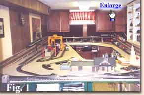
The first requirement is to review the walls/space to which you want to mount a background, to determine if it’s possible and what size background you need. I went on-line to Backdrop Warehouse, reviewed, and made copies of the sizing, pricing, and installation aid material they presented. For my O gauge layout the 36in. X 160 in. long background seemed to be appropriate. Since I would need two matching backgrounds A and B to get the 24-foot run I wanted, the total installed length, allowing for a 3 inch overlap of Sections A and B, would be 2(160-3)= 314inches long and 36 inches high. Looking at Figure 1
|
| The next consideration is the wall construction to which the background is to be mounted. My basement was basically concrete block with textured plaster ceiling. I had installed 1-inch by 2-inch furring strips to the walls and nailed the paneling to the furring strips. The radiused corner structure wall mounting screws would need to be screwed into these furring strips. This meant I would have to determine where the hidden furring strips were located in the corner areas by tapping on the paneled wall to find the non-hollow spots. Additionally, I could see that mounting the background over the pegboard sections and the vertical "plank" grooves in the paneling could be a potential problem if I pasted the background to the wall. I also wanted to move the background along with the movable train tabletops if I moved to another home. I finally concluded I had to design a radiused wood structure to fasten in each corner. I then needed to run new smooth paneling along the existing wall and the newly installed radiused corner structures for the full 24-foot length of the background.
|
|
To determine how the 24-foot background would fit in, I made a sketch to a scale of 1in. =2ft, which for my train room with a size of 8ft. - 10in. by 20 ft., fits nicely on an 8 ½ inch by 11inch sheet. However, the sketches herein are not to scale and show only the basic "how-to’s". |
|
Now let’s calculate a sample problem. From the Backdrop Warehouse web site literature we learned that for an O gauge layout for a matched A and B (12 ft. each) set the total length allowing for the 3 inch overlap, would be 314 inches long as stated herein on the 1st paragraph, page 1. Let’s assume your train room is 14 foot long by 10 foot wide and that your train tabletop is 11 foot long and fills the train room like that shown in Sketch 1. Let’s further assume you want to put a 36-inch radius in each corner. Then A+B’=11ft.x 12in/ft=132in.,or A=132in.-B’. Then A=132-36=96in. In like manner C=10ft.-(B’+D’)= 120in-(36in.+36in.)= 48in. To determine E we use the equation E= Total background length - (A+B+C+D) where B and D are the radial lengths. Assuming r= radius=36in., then B or D =2II r/4=2 x 3.1416x36/4 = 56.55 in. and E= 314 - (A + B +C +D) E=314in.-(96in. + 56.55in. +48 in. + 56.55 in.) E= 314in.-(257.10 in.)= 56.9 in. = 4ft.-8 7/8 in. Now if A must equal E in length, our equation would be Total background length = 2A+B+C+D,or 314= 2A +(B +C +D) 314in.=2A+ (56.55in. + 48in. + 56.55 in.) 314in.= 2A+( 161.1 in.) and A=(314-161.1)/2 =76.45 in. = 6 ft.-4 3/8 in. If you wanted your background to go the full length of the table- top at E, then Total length = A +B +C +D +E Total background length = 96 in. + 56.55 in. + 48 in. +56.55 in. + 96 in. = 353.1 in. = 29 ft. – 5 3/32 in. For this length you would need three 10 foot backgrounds A + B + C to order from Backdrop Warehouse, unless you decide you want two or three different scenes for your background. Discuss your needs with Backdrop Warehouse. NOTE: The instructions from hereon assume you have experience with wood structures. If not get an experienced carpenter’s help. |
|
................ |
| On Table 1, B or D radial lengths for 4 different radii
help you size the radius you would need, keeping in mind that the radius you select should be larger than the radius of the track you may use in the corners.
|
|
After installing a radial corner brace structure in each of the two end corners I added the 1/8-in. thick paneling to the existing paneled walls above the tabletop using panel nails. The paneling I used was a 4ft. X 8-ft. medium-density fiberboard from a national manufacturer in which the finished side was white and had random plank grooves. I purchased all of the lumber, paneling, panel nails, screws, and molding from a nationally known home improvement center. I took one of the horizontal radial braces with me to the home improvement center to see if the panels and molding were flexible enough to bend to a 30-in. radius before I made my purchase. Fortunately, I found both paneling and molding which were acceptable. Note also that the home improvement center cut all three 4 ft. x 8 ft. panels down to the 35 in. width by 8 ft. length I needed at no charge.
|
|
......................................
....
|
|
In Figure 5 the right–hand end of the background
is installed.
|
|
|
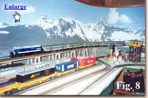
In Figure 7 the addition of the 1 ½ in. flexible stop molding I used (which comes prefinished as shown.), as it curves around the right hand radius corner. Figure 8 is a view of the left-hand radius corner with trains to demonstrate how well the background scale fits in with the O gauge train size. | 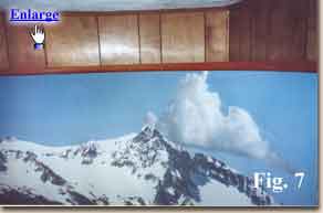
|
.............
|
|
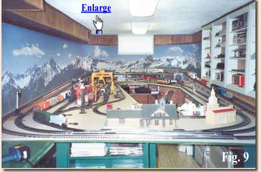
Figure 9 covers the entire 24-ft. of the background and greatly enhances the 3 dimensional appeal of the entire layout. In the 2-radius corners I plan to add mountains, trees, tunnels, and grasses. I have already cut in a small river. The mountains I add are to dovetail into the mountains in the background. I only hope my scenery work will look as real as the background.
|
|
Can you write an Article If you would like to write an article on how you installed your BackDrop, we are interested. Good articles like this one will be included on our web site. Payment is typically around the cost of the backdrops used (limit $300) but may be more or less depending on the number of backdrops involved and the quality of the article.
Many well lighted photos are a must. We may submit good articles for review at major model railroad magazines. All photos and text are your property (except we have the right to use any sent to us on this web site) and arrangements for publication and payment are between you and the magazine. We will match the payment from the magazine up to $200 as long as our company is mentioned as the supplier of the backdrops. We can retouch and improve your photos for no additional charge.
|
 you will note that on the left-hand
wall, I had a 48inch wide yellow peg board section at 2 places and a heater duct (paneled) running along the ceiling about ¾ of the length of the LH wall, and at the end wall I had 2 wall cabinets mounted on each side of the basement window. Since the height from the tabletop to the heater duct was 35 inches I could run the background all the way along the LH wall, across the end wall, and around the RH wall up to the white display shelves which stuck out almost 5 inches from the paneled wall. Since the height from the tabletop to the bottom of the window was 26 3/8 inches, I would lose some of the picture going around the window. Obviously, I would have to remove the 2 wall cabinets at the end wall in order to put in a 24-foot background with radiusing at the 2 corners (These 2 cabinets were moved to the opposite end of the train room).
you will note that on the left-hand
wall, I had a 48inch wide yellow peg board section at 2 places and a heater duct (paneled) running along the ceiling about ¾ of the length of the LH wall, and at the end wall I had 2 wall cabinets mounted on each side of the basement window. Since the height from the tabletop to the heater duct was 35 inches I could run the background all the way along the LH wall, across the end wall, and around the RH wall up to the white display shelves which stuck out almost 5 inches from the paneled wall. Since the height from the tabletop to the bottom of the window was 26 3/8 inches, I would lose some of the picture going around the window. Obviously, I would have to remove the 2 wall cabinets at the end wall in order to put in a 24-foot background with radiusing at the 2 corners (These 2 cabinets were moved to the opposite end of the train room).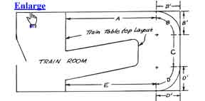 Sketch 1 shows a rectangular room where a radius is shown in each of 2 corners. We show here the space where the background is to be installed. The total length of the background is shown as
A+B+C+D+E. From your math classes you learned that the radial length of a quarter of a circle, such as B or D, would be 2IIr/4,where II is a constant =3.1416.
Sketch 1 shows a rectangular room where a radius is shown in each of 2 corners. We show here the space where the background is to be installed. The total length of the background is shown as
A+B+C+D+E. From your math classes you learned that the radial length of a quarter of a circle, such as B or D, would be 2IIr/4,where II is a constant =3.1416.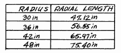 For example if you run an 042 inch diameter track in the corner (21-inch radius), then select at least a 30 in. corner radius for the
curved structure so as to give your trains adequate running clearance around the
corners. sketch 2 shows the radial corner brace structure details and
in Figure 2,
For example if you run an 042 inch diameter track in the corner (21-inch radius), then select at least a 30 in. corner radius for the
curved structure so as to give your trains adequate running clearance around the
corners. sketch 2 shows the radial corner brace structure details and
in Figure 2, 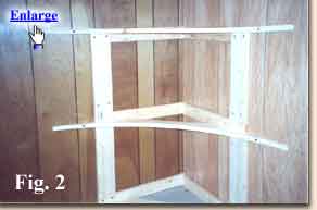 the structure mounted in the corner. I used 3 horizontal radial braces equally spaced. Since I used a 30 in. radius for my structure, I purchased #3 white pine shelving,
nominally 1in x 12 in. but was actually ¾ in x 11 ¼ inch. Three quarter inch thick plywood may be used if deck screws can be screwed into the edges without splitting out. (The plywood I first tried had very hard glue and softwood sections and forced the screws to split out.).
In Table 2,
the structure mounted in the corner. I used 3 horizontal radial braces equally spaced. Since I used a 30 in. radius for my structure, I purchased #3 white pine shelving,
nominally 1in x 12 in. but was actually ¾ in x 11 ¼ inch. Three quarter inch thick plywood may be used if deck screws can be screwed into the edges without splitting out. (The plywood I first tried had very hard glue and softwood sections and forced the screws to split out.).
In Table 2, 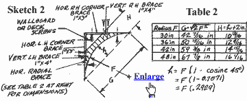 the
minimum width H of the shelving board you would need for each of the 4 different radii. If you choose a radius different from the ones I have shown, you will have to run through all of these equations to calculate new values. For larger than 30 in. radius used in the corners, you could glue/fasten a smaller board alongside the 1 in. x 12 in. shelf board. For example, for a 42-in. radius, you could glue/fasten a 1in. X 6-in. board alongside the 1 in. x 12-in. shelf board. Please note that I have shown the H dimension=h+2 in. in order to provide the minimum width of the board to be at least 2 in. wide, after the radius is cut out. This will provide enough strength in the horizontal radial braces to prevent them from
cracking when the 1/8-in. thick paneling is nailed to them.
the
minimum width H of the shelving board you would need for each of the 4 different radii. If you choose a radius different from the ones I have shown, you will have to run through all of these equations to calculate new values. For larger than 30 in. radius used in the corners, you could glue/fasten a smaller board alongside the 1 in. x 12 in. shelf board. For example, for a 42-in. radius, you could glue/fasten a 1in. X 6-in. board alongside the 1 in. x 12-in. shelf board. Please note that I have shown the H dimension=h+2 in. in order to provide the minimum width of the board to be at least 2 in. wide, after the radius is cut out. This will provide enough strength in the horizontal radial braces to prevent them from
cracking when the 1/8-in. thick paneling is nailed to them. 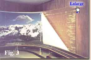 Please note also that the 3 panels laid end to end covered only 24ft. X 12 in./ft.=288 in. and I needed 314 inches to support the background. I cut 2 pieces of 13 in. X 35-in. panels from the leftover 13in. X 8ft. panels to make up the difference. The finished side of this paneling was white with random plank grooves. I mounted that side inward so that the smooth, unfinished side was on the outside. I then mounted the background to the smooth side.
See Figure 3. It takes two people to install the background. Please note that we installed the background from left to right, first installing Sheet A.
Please note also that the 3 panels laid end to end covered only 24ft. X 12 in./ft.=288 in. and I needed 314 inches to support the background. I cut 2 pieces of 13 in. X 35-in. panels from the leftover 13in. X 8ft. panels to make up the difference. The finished side of this paneling was white with random plank grooves. I mounted that side inward so that the smooth, unfinished side was on the outside. I then mounted the background to the smooth side.
See Figure 3. It takes two people to install the background. Please note that we installed the background from left to right, first installing Sheet A.
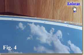 When we came to the end of Sheet A, we matched Sheet B with the correct overlap and then glued Sheet A and B together using rubber cement. After it had dried for about an hour, we cleaned off the excess cement and continued stapling the background to the 1/8 in. added paneling. Figure 4
shows a close-up of the background installed over 1/8 in. paneling in one of the radiused corners. I used 5/16-in. staples in a spring- loaded staple gun to mount the background and I used the 1in. + margin paper trimmed from the background, to add strength to the fastening of the background to the paneling.
When we came to the end of Sheet A, we matched Sheet B with the correct overlap and then glued Sheet A and B together using rubber cement. After it had dried for about an hour, we cleaned off the excess cement and continued stapling the background to the 1/8 in. added paneling. Figure 4
shows a close-up of the background installed over 1/8 in. paneling in one of the radiused corners. I used 5/16-in. staples in a spring- loaded staple gun to mount the background and I used the 1in. + margin paper trimmed from the background, to add strength to the fastening of the background to the paneling.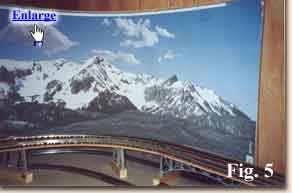 As previously noted, at least two people need to install the background, one person to staple and one person to keep unrolling the background.
Any free hand is needed to keep stretching the background as as taut as possible. It is also necessary to put the staples much closer together around the
radius corners. Figure 6 shows the clearance between the 042-in. track and the installed background at the
As previously noted, at least two people need to install the background, one person to staple and one person to keep unrolling the background.
Any free hand is needed to keep stretching the background as as taut as possible. It is also necessary to put the staples much closer together around the
radius corners. Figure 6 shows the clearance between the 042-in. track and the installed background at the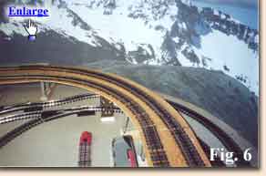 left-hand radiused corner. The elevated main track butts up against the straight portion of the background
in Figure 6, but moves out 10 to 12 in. away from the background as it turns past the
radius corner and continues on at a slight angle to the end wall. This was done on purpose to give a more 3 dimensional depth to the background scene.
left-hand radiused corner. The elevated main track butts up against the straight portion of the background
in Figure 6, but moves out 10 to 12 in. away from the background as it turns past the
radius corner and continues on at a slight angle to the end wall. This was done on purpose to give a more 3 dimensional depth to the background scene.