![]()
Curved Corner Frame Construction and Background Installation
By Kevin N. O'Brien Peoria, IL
|
Introduction The surfaces for this background installation were finished basement walls. As a result, one of the project goals was to minimize the number of holes that needed to be drilled into the walls themselves. To meet this goal necessitated the creation of a freestanding frame with the background mounted prior to hanging. The shape of the O scale layout is a L shape with a single curved corner. One wall is 10' and the other 12'. This mounting technique draws on some of the ideas presented in articles by Ken Spelke entitled "Frame Construction and Mounting" and also by Hal Estill entitled "How to Install a Curved Corner Background". |
|
Selecting the Proper Backdrop Size Clearly, the dimensions called for in this installation were not going to be accommodated by a single backdrop. The question was how many images would be required and at what length. The fact that it was an O Scale Layout dictated that the 36' backdrop height would be appropriate. The first step of determining the number of backdrops is to calculate the continuous length required by the backdrop. This was accomplished using a spreadsheet and the product information contained in the Backdrop Warehouse site. A sample of the spreadsheet follows. Note the deductions necessary to remove the labels and overlap.
|
|
|
|
Frame Construction Due to the length of the two frames that will be joined by the curved corner, the ability to find straight lumber was going to be a challenge. The final lumber purchase list follows:o 2 1" x 3" x 12' for the frame top and frame bottom for the 12" wall o 2 1" x 3" x 10' for the frame top and frame bottom for the 10" wall o 13 1" x 2" x 28 ¾" for the vertical frame supports The overall vertical dimension of the frame is 34 ¾". The reason for the odd number is that the printed surface on a 36" x 10' backdrop is in fact only 34 ¾". The intention of this construction was to only have the printed surface showing; therefore, the frame was constructed to accommodate only the printed area. The lumberyard does not actually carry lumber in the 1" x 3" dimension for the lengths of 10' and 12'. To accomplish this some 1" x 6" boards were cut in half at the lumberyard for a nominal fee. This was done in an effort to maintain the straightest resulting board possible. Interestingly, the board did warp slightly the moment the saw blade finished the cut and so steps were required throughout the construction to get the frame square. |
|
Wall Frame Assembly The frames were assembled using corner brackets that can be found in aluminum or steel at most home improvement stores.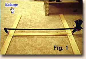 In addition, some steel
plates with screw holes (see picture Backdrop Mounting Bracket
Installation) were used to anchor the outside of the vertical supports to
the top and bottom frame boards to ensure that the frame was rigid and
resisted warping.
The most successful and fastest method to create the frame was to use
a long clamp to hold the vertical frame board to the two horizontal boards
before attaching the corner brackets. This can be seen in
Fig. 1. All corner bracket holes were
predrilled to avoid splitting the wood. This step is repeated until the
entire single framing element is complete. For added strength wood glue
was used at each contact area. Once complete the frame should resemble the
picture in Fig. 2. In addition, some steel
plates with screw holes (see picture Backdrop Mounting Bracket
Installation) were used to anchor the outside of the vertical supports to
the top and bottom frame boards to ensure that the frame was rigid and
resisted warping.
The most successful and fastest method to create the frame was to use
a long clamp to hold the vertical frame board to the two horizontal boards
before attaching the corner brackets. This can be seen in
Fig. 1. All corner bracket holes were
predrilled to avoid splitting the wood. This step is repeated until the
entire single framing element is complete. For added strength wood glue
was used at each contact area. Once complete the frame should resemble the
picture in Fig. 2. 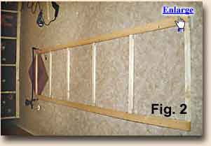 Note you can see the
mounting brackets used to attach the outside vertical supports to the top
and bottom plates. This same construction technique was used to create the
second wall frame. Note you can see the
mounting brackets used to attach the outside vertical supports to the top
and bottom plates. This same construction technique was used to create the
second wall frame.
|
|
................ |
|
Frame Attachment at the Corner
|
|
|
|
Hanging the Frame Prior to hanging the frame, mounting brackets need to be attached to the back of the frame. This was done using the same four holed steel plates used to secure the outside of the frame.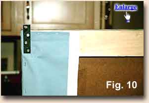 The mounting bracket will
look like Fig. 10. Hold the
frame up to the designated area and mark the bracket holes with a pencil.
Make sure that the frame is flush with both walls in the corner. Remove
the frame and drill holes to accommodate dry wall mollies. Sink the
mollies into the holes at all locations. Bring the frame back into the
installation position and install screws into all bracket locations.
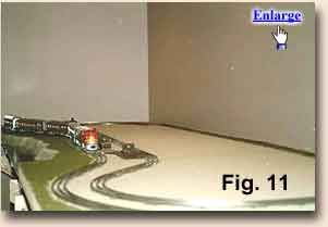
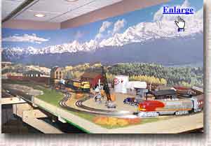
The installation is now complete and an immediate impact to the layout
should be seen. Illustrations of the early stages of layout construction
with the backdrop in place can be see in the
before Fig. 11 and after pictures. The mounting bracket will
look like Fig. 10. Hold the
frame up to the designated area and mark the bracket holes with a pencil.
Make sure that the frame is flush with both walls in the corner. Remove
the frame and drill holes to accommodate dry wall mollies. Sink the
mollies into the holes at all locations. Bring the frame back into the
installation position and install screws into all bracket locations.
The installation is now complete and an immediate impact to the layout
should be seen. Illustrations of the early stages of layout construction
with the backdrop in place can be see in the
before Fig. 11 and after pictures.
|
|
Can you write an Article If you would like to write an article on how you installed your BackDrop, we are interested. Good articles like this one will be included on our web site. Payment is typically around the cost of the backdrops used (limit $300) but may be more or less depending on the number of backdrops involved and the quality of the article.
Many well lighted photos are a must. We may submit good articles for review at major model railroad magazines. All photos and text are your property (except we have the right to use any sent to us on this web site) and arrangements for publication and payment are between you and the magazine. We will match the payment from the magazine up to $200 as long as our company is mentioned as the supplier of the backdrops. We can retouch and improve your photos for no additional charge.
|
 Once the two frames are complete it is time to join them together at
 The curved corner radius was chosen to be 30".
This radius was selected to ensure that there was enough room for the train
to clear the background on its 21" radius curves. 5/8" Plywood scrap
pieces were used to create the curve. A 30" square was drawn on the board.
A nail was lightly driven into a corner of the square. A small thin wire
and pencil were attached to the nail. The pencil should start at one of
the other corners. Trace the ¼ circle on the board by moving the pencil
from one corner to the other. Cut the board along the traced line and you
will end up with the curved corner support for the backdrop. Two other
curves were created the same way. These will be placed into the corner
were the frames are joined together. They are attached at the top, middle,
and bottom of the frame. Screw supports blocks into the vertical framing
structure at the two edges and the corner.
The curved corner radius was chosen to be 30".
This radius was selected to ensure that there was enough room for the train
to clear the background on its 21" radius curves. 5/8" Plywood scrap
pieces were used to create the curve. A 30" square was drawn on the board.
A nail was lightly driven into a corner of the square. A small thin wire
and pencil were attached to the nail. The pencil should start at one of
the other corners. Trace the ¼ circle on the board by moving the pencil
from one corner to the other. Cut the board along the traced line and you
will end up with the curved corner support for the backdrop. Two other
curves were created the same way. These will be placed into the corner
were the frames are joined together. They are attached at the top, middle,
and bottom of the frame. Screw supports blocks into the vertical framing
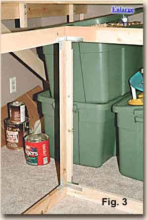
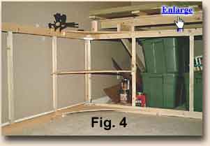
structure at the two edges and the corner. 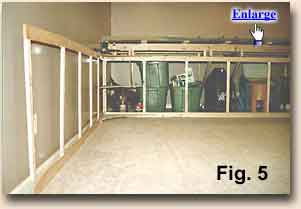 This will create a platform for
the plywood to rest on. Place the curved corner piece on the supports. A
single screw down into each support block held the curved board in place.
The finished product can be seen in Fig. 4. The frame is now complete and should resemble
Fig. 5.
This will create a platform for
the plywood to rest on. Place the curved corner piece on the supports. A
single screw down into each support block held the curved board in place.
The finished product can be seen in Fig. 4. The frame is now complete and should resemble
Fig. 5.
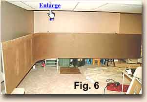 The hardboard was
attached to the frame using small screws. It is vital that the hardboard
starts straight (true) or by the time you get to the corner, the board will
want to dip or rise above the frame. Once the three pieces are attached
the frame will look like Fig. 6. To finish the surface, the screw holes and seams were
covered with packing tape.
The hardboard was
attached to the frame using small screws. It is vital that the hardboard
starts straight (true) or by the time you get to the corner, the board will
want to dip or rise above the frame. Once the three pieces are attached
the frame will look like Fig. 6. To finish the surface, the screw holes and seams were
covered with packing tape.
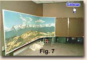 The third person held the remaining backdrop in
a roll. The backdrop was installed in two-foot sections at a time. A
thorough coat of the adhesive was applied to the two-foot section. The
backdrop was placed against the hardboard and rolled into place. The spray
adhesive was easy to apply but the residual spray coats the floor and gets
very sticky, be sure to use drop clothes in any finished area. This
process continues until one of the prints is completely installed. It
should look like Fig. 7. It
is now time to overlap the first image with the second to create
the transition. The first step is to cut off the
border of the second
image on the side that will transition with the first image. This is done
using a very sharp razor blade and a straight edge. If the blade cuts from
the front of the backdrop there is the possibility that you will be able to
see a thin white strip from the underlying media.
The third person held the remaining backdrop in
a roll. The backdrop was installed in two-foot sections at a time. A
thorough coat of the adhesive was applied to the two-foot section. The
backdrop was placed against the hardboard and rolled into place. The spray
adhesive was easy to apply but the residual spray coats the floor and gets
very sticky, be sure to use drop clothes in any finished area. This
process continues until one of the prints is completely installed. It
should look like Fig. 7. It
is now time to overlap the first image with the second to create
the transition. The first step is to cut off the
border of the second
image on the side that will transition with the first image. This is done
using a very sharp razor blade and a straight edge. If the blade cuts from
the front of the backdrop there is the possibility that you will be able to
see a thin white strip from the underlying media.
 A successful fix to this
problem is to cut the backdrop from the back ensuring that the blade is
angled away from cut edge (angled into the image, away from the
border).
This will cut the white backing material slightly inside the cut of the
printed material and will ensure that it is not seen from the front.
As with the first, the second image is marked on the back using a
pencil where the bottom of the border should be on the topside of the
print. To ensure a tight bond of the second image over the first, a
cardboard screen was placed over the first image to protect it while the
adhesive was sprayed onto the overlap area and first two feet of the
hardboard. Position the second image to ensure a smooth transition and
roll it into place. The same mounting procedure was followed until the
second image was completed.
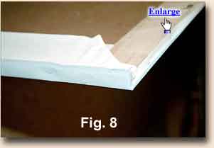
Once the two images are attached to the hardboard, the
borders can be
folded over and stapled to the top, sides, and bottom of the frame.
Details of how to handle corner folds can be seen in
Fig. 8.
A successful fix to this
problem is to cut the backdrop from the back ensuring that the blade is
angled away from cut edge (angled into the image, away from the
border).
This will cut the white backing material slightly inside the cut of the
printed material and will ensure that it is not seen from the front.
As with the first, the second image is marked on the back using a
pencil where the bottom of the border should be on the topside of the
print. To ensure a tight bond of the second image over the first, a
cardboard screen was placed over the first image to protect it while the
adhesive was sprayed onto the overlap area and first two feet of the
hardboard. Position the second image to ensure a smooth transition and
roll it into place. The same mounting procedure was followed until the
second image was completed.
Once the two images are attached to the hardboard, the
borders can be
folded over and stapled to the top, sides, and bottom of the frame.
Details of how to handle corner folds can be seen in
Fig. 8. 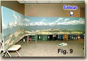 It was necessary to cut slits in the
border around the corner to get the border to lay flat against the frame. Once all of the
borders are folded over and stapled, a final application of packing tape
to the folded edge ensures that it will be smooth and that no ripples will
be visible from the front. The final product can be seen prior to hanging
in Fig. 9.
It was necessary to cut slits in the
border around the corner to get the border to lay flat against the frame. Once all of the
borders are folded over and stapled, a final application of packing tape
to the folded edge ensures that it will be smooth and that no ripples will
be visible from the front. The final product can be seen prior to hanging
in Fig. 9.